2 Phase Closed Loop FWD Series
Stepping Motors
- New 2 phase Control System allows Stepping motor to operate at High Speeds
- 0.72 can be achieved (same as 5 phase motors) and can be divided by 80 (or 0.009 deg)
- Unique out of step position can be detected (only for motor shaft speeds greater than 500 rpm)
- Available using our 2 phase Square size 17 and size 23 stepper motors.
Unit of Measure
| Items |
 /Asset/FWD2-.jpg /Asset/FWD2-.jpg FWD2B1P15-11 169 Millinewton Meter (mN·m) Static Torque 2 Phase Closed Loop FWD Series |
 /Asset/FWD2-.jpg /Asset/FWD2-.jpg FWD2B1P15-21 314 Millinewton Meter (mN·m) Static Torque 2 Phase Closed Loop FWD Series |
 /Asset/FWD2-.jpg /Asset/FWD2-.jpg FWD2B1P15-31 427 Millinewton Meter (mN·m) Static Torque 2 Phase Closed Loop FWD Series |
 /Asset/FWD2-.jpg /Asset/FWD2-.jpg FWD2B1P15-41 918 Millinewton Meter (mN·m) Static Torque 2 Phase Closed Loop FWD Series |
 /Asset/FWD2-.jpg /Asset/FWD2-.jpg FWD2B2P15-11 491 Millinewton Meter (mN·m) Static Torque 2 Phase Closed Loop FWD Series |
|||||
| Type | N/A 2 Phase Hybrid Square KH Series | |||||||||
| Applicable Motor | N/A KH42HM2-951 | N/A KH42JM2-951 | N/A KH42KM2-951 | N/A KH60JM2-951 | N/A KH56JM2-951 | |||||
| Motor Frame Size | N/A 42 x 42 mm1.564 x 1.564 in | N/A 42 x 42 mm1.564 x 1.564 in | N/A 42 x 42 mm1.564 x 1.564 in | N/A 60 x 60 mm2.362 x 2.362 in | N/A 56 x 56 mm2.205 x 2.205 in | |||||
| No. of Phases | N/A 2 | |||||||||
| Basic Resolution | N/A 0.72 in | |||||||||
| Excitation System | N/A Basic Resolution (Step) Micro Step (n=1, 2, 4, 8, 10, 20, 40, 80) | |||||||||
| Current | N/A 0.8 A | N/A 0.8 A | N/A 1.2 A | N/A 2.0 A | N/A 2.0 A | |||||
| Rotor Inertia | N/A 0.54 x 10³ oz·in² | N/A 0.79 x 10³ oz·in² | N/A 1.2 x 10³ oz·in² | N/A 3.89 x 10³ oz·in² | N/A 1.63 x 10³ oz·in² | |||||
| Power Specifications | N/A 24VDC, 2.0A | N/A 24VDC, 2.0A | N/A 24VDC, 2.5A | N/A 24VDC, 4.0A | N/A 24VDC, 3.0A | |||||
| Driver Mass | N/A 0.51 lb | |||||||||
| Motor Mass | N/A 0.44 lb | N/A 0.57 lb | N/A 0.79 lb | N/A 1.32 lb | N/A 0.88 lb | |||||
| Insulation Class (Motor Section) | N/A Equivalent to class | |||||||||
| Insulation Resistance (Motor Section) | N/A 500VDC 100 MO min | |||||||||
| Dielectric Strength (Motor Section) | N/A 500VAC 50Hz 1min | |||||||||
| Max. Static Torque | N/A 169 mN·m23.9 oz.in | N/A 314 mN·m44.5 oz.in | N/A 427 mN·m60.5 oz.in | N/A 918 mN·m130 oz.in | N/A 491 mN·m69.5 oz.in | |||||
| Working Ambient Temperature (Driver Section) | N/A 0~+50 ºC | |||||||||
| Working Ambient Temperature (Motor Section) | N/A -10~+50 ºC | |||||||||
| Working Ambient Humidity (Driver Section) | N/A 0~+50 ºC | |||||||||
| Working Ambient Humidity (Motor Section) | N/A 15~85 % | |||||||||
| Storage Ambient Temperature (Driver Section) | N/A 0~+50 ºC | |||||||||
| Storage Ambient Temperature (Motor Section) | N/A -20~+70 ºC | |||||||||
| Storage Ambient Humidity (Driver Section) | N/A 35~85 % | |||||||||
| Storage Ambient Humidity (Motor Section) | N/A 10~85 % | |||||||||
| Torque Curves |
N/A
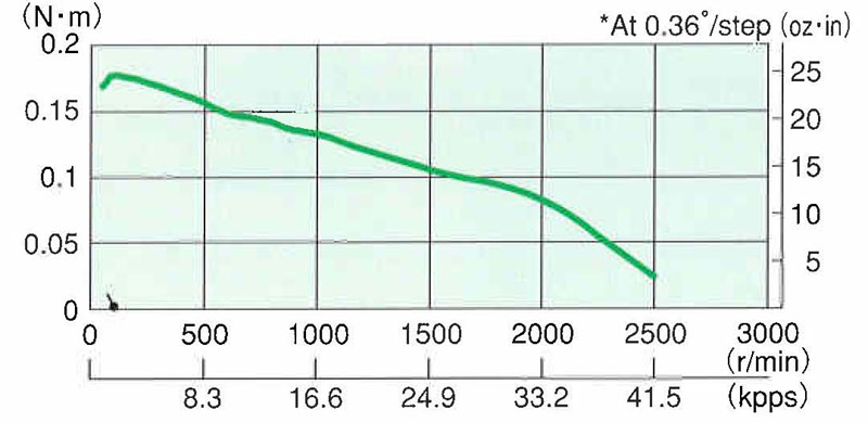 a1960.jpg |
N/A
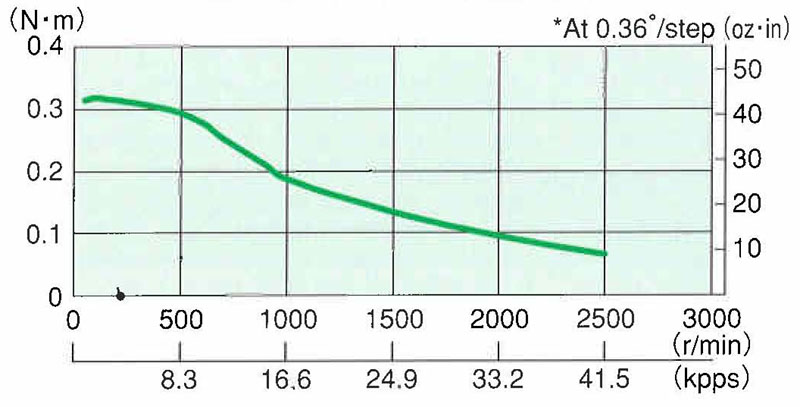 a1962.jpg |
N/A
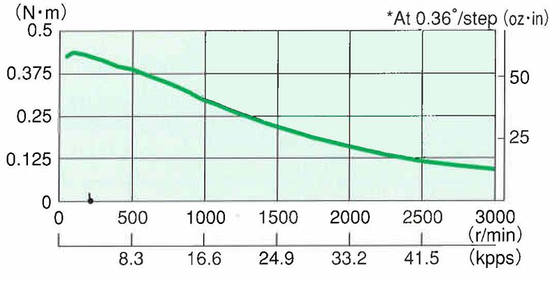 a1964.jpg |
N/A
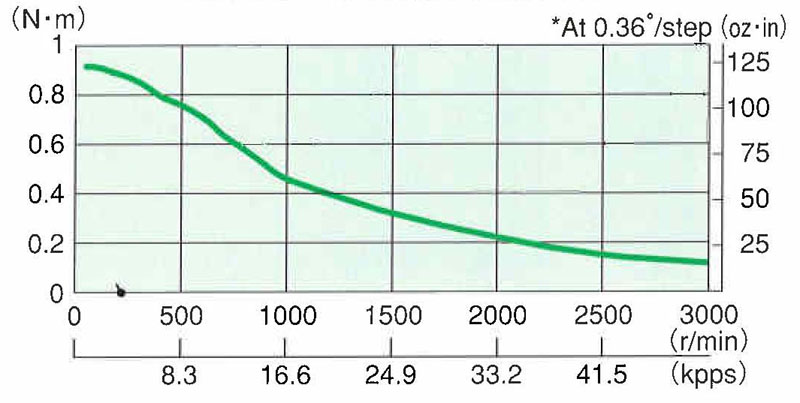 a1966.jpg |
N/A
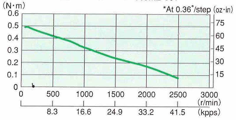 a1970.jpg |
|||||
| Dimensions |
N/A
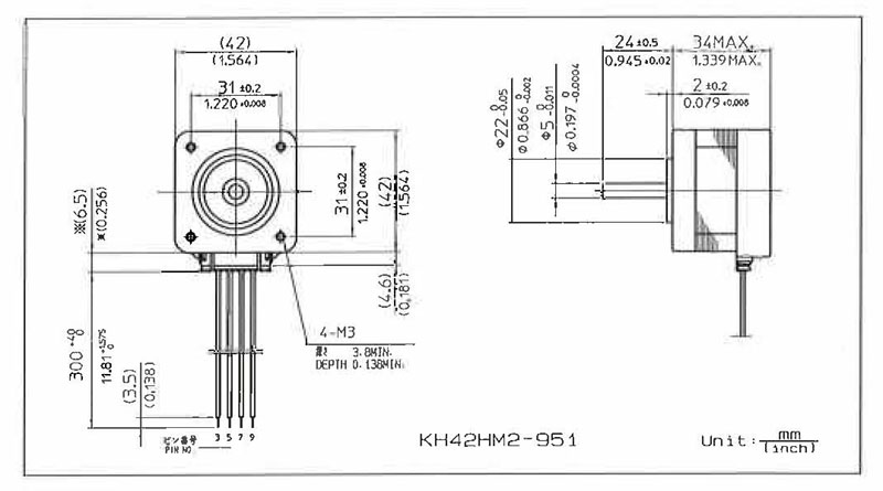 Dimensions 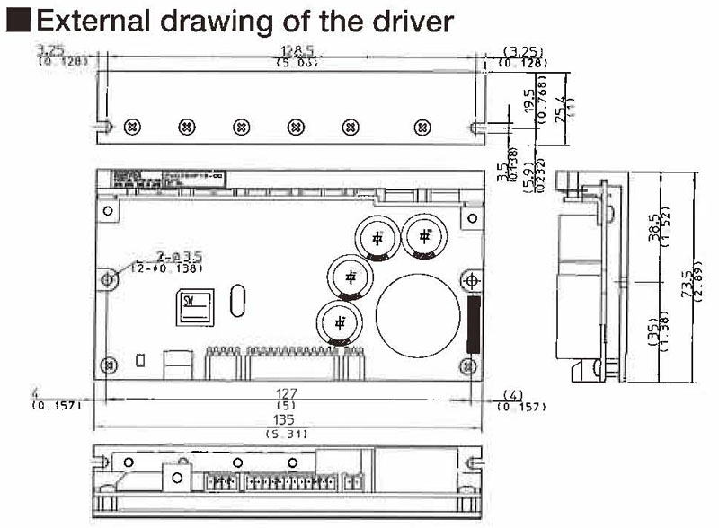 External Drawing of the Driver  Wiring Diagram |
N/A
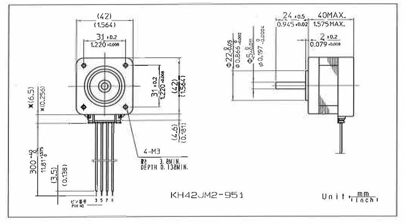 Connection Diagrams  External Drawing of the Driver  Wiring Diagram |
N/A
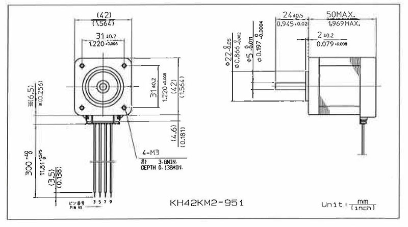 Connection Diagrams  External Drawing of the Driver  Wiring Diagram |
N/A
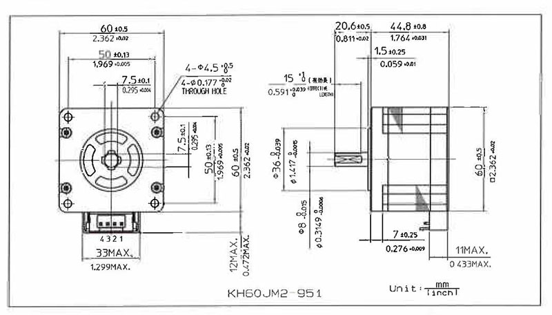 Connection Diagrams  External Drawing of the Driver  Wiring Diagram |
N/A
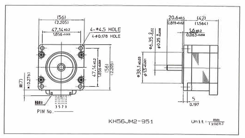 Connection Diagrams  External Drawing of the Driver  Wiring Diagram |
|||||
| Additional Information |
N/A
 Allowable Radial Load and Allowable Thrust Load 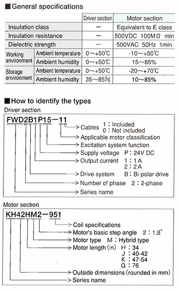 Driver and Motor Selection Guide 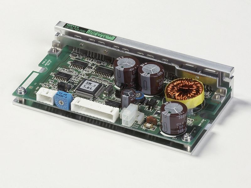 Driver Picture 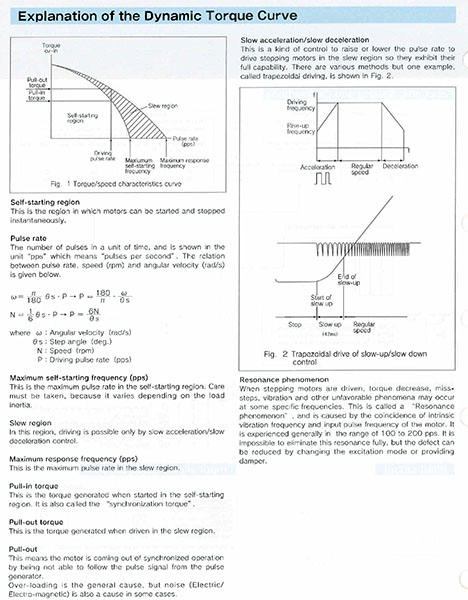 Explanation of Dynamic Torque Curves  Installation Location 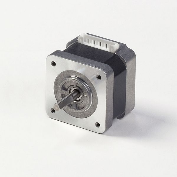 KH42 B900 Series 42mm, 2-Phase Stepping Motors (1.8 Degree/Step) - Nema 17 (KH4234-B90101) 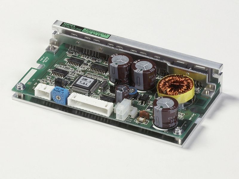 Stepping Servos FWD Series  System Configuration  Torque Stepping Drawing |
N/A
 Allowable Radial Load and Allowable Thrust Load  Driver and Motor Selection Guide  Driver Picture  Explanation of Dynamic Torque Curves  Installation Location 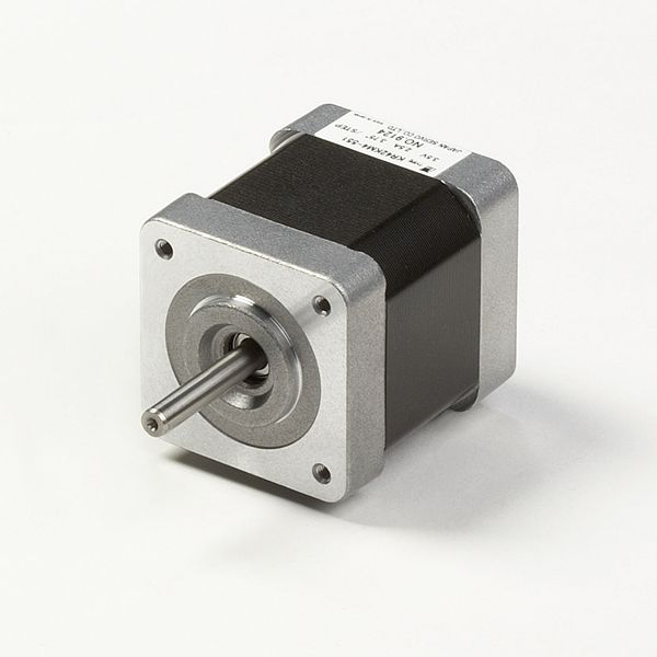 KH42 B900 Series 42mm, 2-Phase Stepping Motors (1.8 Degree/Step) - Nema 17 (KH4238-B95101)  Stepping Servos FWD Series  System Configuration  Torque Stepping Drawing |
N/A
 Allowable Radial Load and Allowable Thrust Load  Driver and Motor Selection Guide  Driver Picture  Explanation of Dynamic Torque Curves  Installation Location 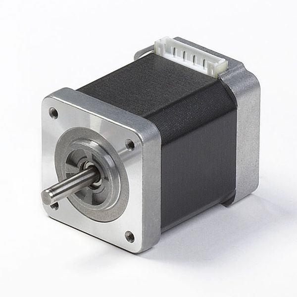 KH42 B900 Series 42mm, 2-Phase Stepping Motors (1.8 Degree/Step) - Nema 17 (KH4254)  Stepping Servos FWD Series  System Configuration  Torque Stepping Drawing |
N/A
 Allowable Radial Load and Allowable Thrust Load  Driver and Motor Selection Guide  Driver Picture  Explanation of Dynamic Torque Curves  Installation Location  KH56 Series 2-Phase Hybrid Stepping Motors (1.8 Degree/Step) - Nema 23 (KH56JM2)  Stepping Servos FWD Series  System Configuration  Torque Stepping Drawing |
N/A
 Allowable Radial Load and Allowable Thrust Load  Driver and Motor Selection Guide  Driver Picture  Explanation of Dynamic Torque Curves  Installation Location  KH56 Series 2-Phase Hybrid Stepping Motors (1.8 Degree/Step) - Nema 23 (KH56JM2)  Stepping Servos FWD Series  System Configuration  Torque Stepping Drawing |
|||||
| Customize | N/A Custom Designs | |||||||||
|
|
||||||||||


